Understanding Vehicle Motion
ESC & Handling Validation with Dynamics Duo
The VBOX 4 and IMU05 combine to deliver CG-referenced, time-aligned measurement of vehicle motion – built for ESC calibration, handling balance work, and regulatory compliance testing.
THE CHALLENGE
Why ESC and handling tests are hard to measure accurately
Fast manoeuvres, system interventions, and poor sensor placement combine to make cause-and-effect ambiguous. These are the problems Dynamics Duo is designed to resolve.
Signals that don't share a reference
Data biased by mounting position
Sensors, such as GNSS antennas mounted at roof height exaggerates roll and introduces lever-arm errors in speed and lateral acceleration. During aggressive manoeuvres, this can compound into significant measurement errors.
Noise that obscures stability margins
Subtle changes in handling balance – understeer gradient shifts, yaw rate gain variation – are easily masked by sensor noise when data quality is marginal. ESC tuning decisions made on noisy data carry risk.
Separating driver action from system response
During ESC activation events, understanding whether the vehicle's behaviour was caused by the driver or the stability system requires simultaneous, synchronised capture of both. Any gap in the data creates ambiguity.
THE SYSTEM
Two instruments. One coherent measurement.
VBOX 4 provides high-accuracy GNSS-based speed, position and trajectory. IMU05 adds low-noise inertial data at the CG. Together they produce a single unified picture of vehicle motion.
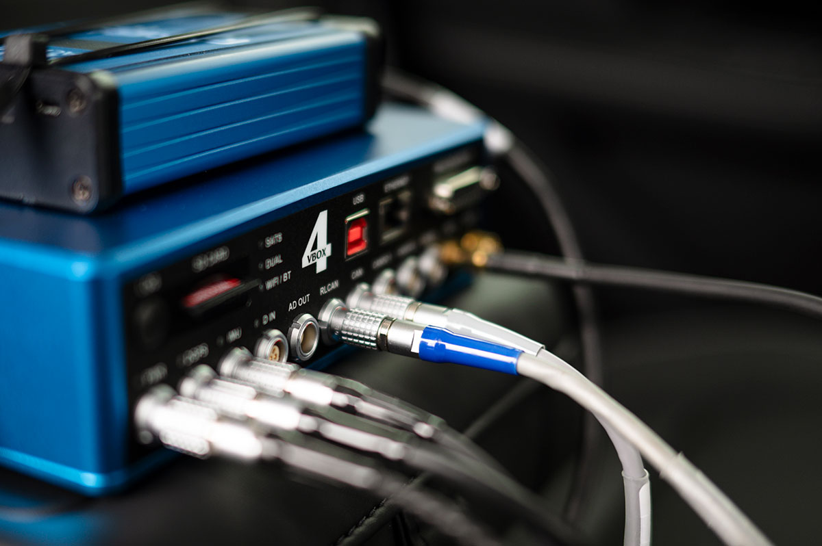
VBOX 4
100 Hz GNSS measurement engine with dual-antenna heading, CAN data logging and real-time output. The foundation for speed, position and path measurement.
- GNSS update rate 100 Hz
- Position accuracy (standalone)H: 1.2 m; V: 1.8 m
- Velocity accuracy 0.1 km/h RMS
- CAN ports 2 × CAN + 2 x CAN FD
- RTK accuracy (optional) V: 10 mm + 0.8 ppm·BL; H: 5 mm + 0.5 ppm·BL
- Slip angle calculation At up to 5 vehicle positions
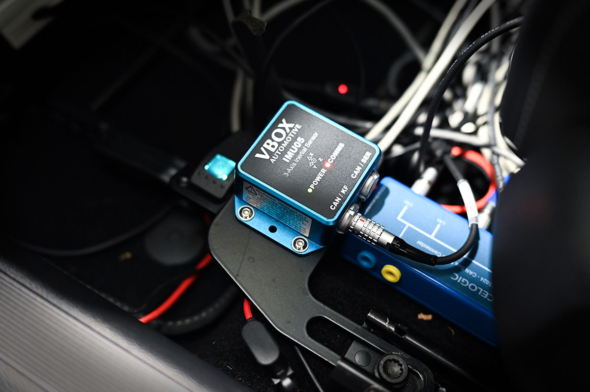
IMU05
Low-noise 6-axis inertial measurement unit. Mounted at a convenient location on the vehicle; lever-arm compensation translates all measurements to the centre of gravity for analysis.
- Gyro range ±450°/s
- Gyro bias stability ±1.2°/h
- Angle random walk 0.08°/√h
- Accel range ±4 g
- Accel bias stability 14 µg
- IP rating 67
WHY DYNAMICS DUO
Four things engineers need. All resolved in one setup.
01 / 04
CG-referenced vehicle motion
For handling analysis, measurements must reflect how the vehicle moves at its true centre of gravity, not at an arbitrary mounting point.
- Speed and slip angle referenced to the CG
- Longitudinal and lateral acceleration at the CG, not the roof
- Accurate vehicle trajectory for path and corridor analysis
Clean data in dynamic manoeuvres
Noisy or biased inertial data makes vehicle behaviour hard to read, especially in the transient phase where accurate measurement is most critical for ESC validation.
- Pitch and roll measured cleanly during rapid steering events
- Accurate Yaw rate and lateral acceleration in aggressive manoeuvres
- Low noise, low drift measurements for consistent testing
Clear separation of driver and ESC actions
To understand ESC behaviour, you need to know what the driver did and what the system did in response. This requires synchronised capture of all relevant signals:
- Vehicle CAN data such as ESC status, steering angle and wheel speeds
- Yaw rate and slip angle time-aligned with vehicle CAN data
One setup across the full programme
From regulatory ESC tests to steady-state handling and OEM development work, a single installation covers the measurement requirements throughout the stability programme.
- ISOFIX mount for fast vehicle changes (typically < 10 min swap)
- Real-time output confirms run validity on track
- Compatible with RTK correction for path-accuracy-critical tests
REGULATORY & INDUSTRY STANDARDS
Standards and test frameworks supported
Dynamics Duo provides the measurements needed to assess response, stability, and intervention behaviour across a broad range of regulatory and OEM test requirements.
| Standard | Manoeuvre | Measurement challenge | How Dynamics Duo helps |
|---|---|---|---|
| UNECE R140ESC Regulation (Global) | Sine with dwell, lane change on low-µ | Separating driver input from ESC action; yaw response timing under intervention | CG-referenced yaw, slip and lateral acceleration — time-aligned with CAN ESC status |
| FMVSS 126US Federal Standard | Sine with dwell (1 Hz, 0.5 Hz variants) | Steering–yaw phase lag; noisy yaw in high-frequency transients | Low-lag yaw and slip on one time base — accurate intervention timing measurement |
| ISO 3888-2Double Lane Change | Double lane change (elk test) | Path corridor compliance within tight tolerances; roof-biased motion during transients | CG-true trajectory and yaw for corridor analysis RTK recommended |
| ISO 3888-1Obstacle Avoidance | Obstacle avoidance lane change | Speed-dependent path deviation; yaw overshoot after course exit | Slip angle and yaw time-history; trajectory vs cone corridor overlay |
| ISO 4138Steady-State Circular | Constant radius / constant speed sweep | Noise masks understeer gradient changes; CG vs wheel measurement discrepancy | Low-noise yaw rate gain and lateral acceleration at the CG |
| ISO 7401Transient Response | Step steer, ramp steer, sinusoidal steer | Delayed or noisy signals obscure rise time and overshoot measurement | Time-aligned steering, yaw and slip with low lag — accurate response time measurement |
| ISO 11026High-Speed Sinusoidal | Sine sweep (frequency ramp) | Lateral acceleration and yaw rate amplitude accuracy at 1–2 Hz; phase measurement | High sample rate GNSS-IMU fusion maintains accuracy through the frequency range |
| OEM ESC ProtocolsInternal / Benchmarking | Manufacturer-specific calibration sequences | Inconsistent reference points when comparing variants or competitors | Single CG-referenced motion reference simplifies variant-to-variant benchmarking |
- Manoeuvre
- Sine with dwell, lane change on low-µ
- Challenge
- Separating driver input from ESC action; yaw response timing under intervention
- How Dynamics Duo helps
- CG-referenced yaw, slip and lateral acceleration — time-aligned with CAN ESC status
- Manoeuvre
- Sine with dwell (1 Hz, 0.5 Hz variants)
- Challenge
- Steering–yaw phase lag; noisy yaw in high-frequency transients
- How Dynamics Duo helps
- Low-lag yaw and slip on one time base — accurate intervention timing measurement
- Manoeuvre
- Double lane change (elk test)
- Challenge
- Path corridor compliance within tight tolerances; roof-biased motion during transients
- How Dynamics Duo helps
- CG-true trajectory and yaw for corridor analysis RTK recommended
- Manoeuvre
- Obstacle avoidance lane change
- Challenge
- Speed-dependent path deviation; yaw overshoot after course exit
- How Dynamics Duo helps
- Slip angle and yaw time-history; trajectory vs cone corridor overlay
- Manoeuvre
- Constant radius / constant speed sweep
- Challenge
- Noise masks understeer gradient changes; CG vs wheel measurement discrepancy
- How Dynamics Duo helps
- Low-noise yaw rate gain and lateral acceleration at the CG
- Manoeuvre
- Step steer, ramp steer, sinusoidal steer
- Challenge
- Delayed or noisy signals obscure rise time and overshoot measurement
- How Dynamics Duo helps
- Time-aligned steering, yaw and slip with low lag
- Manoeuvre
- Sine sweep (frequency ramp)
- Challenge
- Lateral acceleration and yaw rate amplitude accuracy at 1–2 Hz; phase measurement
- How Dynamics Duo helps
- High sample rate GNSS-IMU fusion maintains accuracy through the frequency range
- Manoeuvre
- Manufacturer-specific calibration sequences
- Challenge
- Inconsistent reference points when comparing variants or competitors
- How Dynamics Duo helps
- Single CG-referenced motion reference simplifies variant-to-variant benchmarking
WHAT YOU CAN MEASURE
Objective, reproducible parameters for dynamics testing
The parameters below are direct outputs of the VBOX 4 + IMU05 combination unless noted. All are logged, time-aligned and available for real-time display and post-test analysis.
Steering & response
- Yaw rate
- Steering angle
- Lateral acceleration (CG)
- Understeer / oversteer behaviour
Steering angle: sourced from vehicle CAN or optional sensor – not a native GNSS/IMU output.
Body slip & balance
- Body slip angle at the CG
- Lateral acceleration at the CG
- Roll and pitch angle
Individual tyre slip angles require additional wheel angle information.
Path & corridor
- Vehicle trajectory
- ISO 3888-1/2 corridor compliance
- Speed and distance throughout test
- Lateral deviation from centreline
Centimetre-level path accuracy requires RTK correction (NTRIP or base station).
ESC & stability systems
- ESC activation timing (via CAN)
- Yaw change at and after ESC intervention
- Wheel speed and slip measurement
SOFTWARE & ANALYSIS
VBOX Test Suite – Analysis built for dynamics work

VBOX Test Suite supports your entire test workflow – from live track-side monitoring through to regulatory submission – all within a single platform. Engineers can compare runs, overlay channels from identical test conditions, and export to downstream tools without conversion.
- Live data display for real-time pass/fail feedback at the trackside
- Vehicle trajectory overlay for path comparison
- Multi-run overlay with channel alignment – compare back-to-back or vehicle-to-vehicle
- Customisable workspace combining charts, maps, and synchronised HD video
- Automated report generation for regulatory submissions
Data export formats
All VBOX data can be exported for use in other analysis tools such as MATLAB and Python.
VBOX CAN output is available for real-time integration with external data acquisition systems.
Ready to discuss your ESC or handling programme?
Our engineers understand the demands of stability and handling validation work. Contact us to discuss your specific test requirements, vehicle types and preferred standards.

