
Measuring attitude with VBOX 4
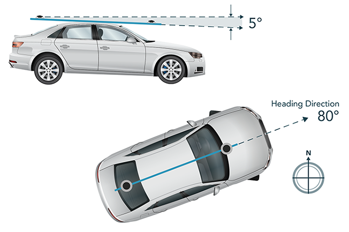
By using two GNSS antennas, the VBOX 4 Dynamics measures all the normal VBOX GPS parameters, plus the azimuth and elevation between the antennas, i.e. the direction the antennas are pointing, and the angle between them measured from the horizontal. This allows the unit to measure slip angle, and also pitch angle (or roll angle depending on how the antennas are mounted), all at 100 Hz. This system is ideal for vehicle dynamics testing.
Using an Inertial Measurement Unit (IMU) with a Dual Antenna setup
VBOX 4 is our flagship data logger and offers support for an inertial measurement unit, such as the VBOX IMU, which features a Kalman Filter. This can be used to process the heading parameter and give a cleaner heading with lever arm compensation, which can be seen by comparing heading to raw heading. This ‘cleaner’ heading parameter is then used in the slip angle and translated slip.
True heading is not processed by the Kalman Filter, however the VBOX 4 Dynamics will use the IMU’s yaw rate during translated slip angle calculations. The IMU yaw rate has a lower noise level than the dual antenna yaw rate, resulting in a cleaner translated slip angle measurement parameter set.
Note, this will not have any impact on the standard slip angle channel as it does not require yaw rate for the calculation. Also note that the Kalman filter does not need to be enabled to get this additional benefit.
Using an Inertial Measurement Unit (IMU) with the VBOX 4 provides highly accurate measurements of speed, distance, heading and yaw rate, for applications such as testing Electronic Stability Control with a steering robot.
VBOX IISX
If you do not require an IMU or 100 Hz logging, the VBOX IISX Dual Antenna could be the ideal choice. The two antennas are placed on the vehicle a set distance apart, and the distance is entered into the VBOX using the front panel and display. An algorithm then uses this 'fixed baseline' to determine the relative position and height of each antenna to a few millimetres. This can be done because errors received at one antenna can be used to cancel out errors at the other antenna, given the known distance between the two.


Knowing the relative height gives a very accurate angle between them, and this gives the pitch angle if configured longitudinally (down the roof), and roll angle if configured laterally (across the roof). In both orientations, the slip angle can still be measured, the user just has to apply a 90 degree offset which is available through the front panel.
Note: The slip angle varies across the width of the car, so it is important to place the antenna directly above the point at which you wish to measure this angle. Ground plane antennas can be mounted outside the body of the vehicle using a suitable mount.
The accuracy of the slip angle and pitch angle depend on the separation of the antennas and the quality of the antennas which are used. The wider the separation of the antennas, the better the accuracy you will achieve.